


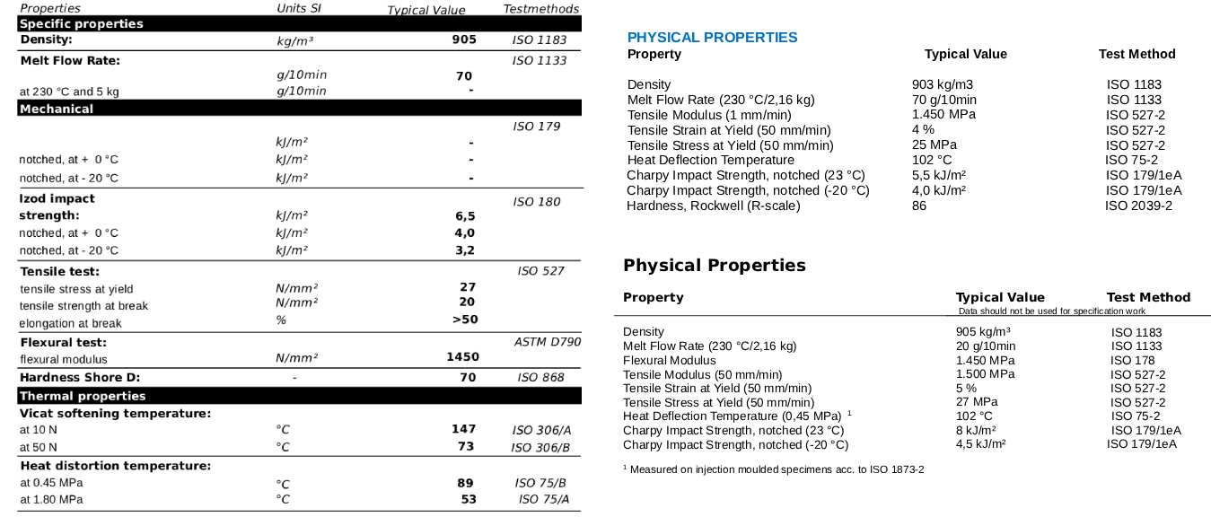
Standards and parameters found in plastic raw material technical data sheets (datasheets) determine the material’s processability, mechanical strength, thermal performance, and response to environmental conditions.
1. Detailed Explanations of Core Terms in Raw Material Datasheets
- Melt Flow Index (MFI) / Melt Mass-Flow Rate (ASTM D1238 – ISO 1133)
- Description: Indicates the amount of molten plastic, in grams, flowing through a calibrated die in 10 minutes under a specified temperature and load.
- Significance: Expresses the material’s fluidity. While a low MFI points to high molecular weight and strength (ideal for extrusion and thick-walled parts); a high MFI provides easy flow and is preferred in injection molding requiring thin walls and fast cycle times.
- Density / Specific Gravity (ASTM D792 – ISO 1183)
- Description: The mass per unit volume of a material.
- Significance: Directly affects part weight, raw material cost, and the material’s degree of crystallinity (e.g., HDPE vs. LDPE). It provides insight into sink/float characteristics and filler ratios.
- Tensile Stress (Yield) / Yield Strength (ASTM D638 – ISO 527-2)
- Description: The stress value at which a material begins to undergo permanent (plastic) deformation.
- Significance: Shows the maximum tensile force the material can bear before deforming under load. High yield strength ensures the material remains rigid under load.
- Tensile Strain (Break) / Elongation at Break (ASTM D638 – ISO 527-2)
- Description: Expresses how much a material’s length can stretch until it breaks, as a percentage (%).
- Significance: Indicates the ductility (flexibility) or brittleness of the material. High elongation at break specifies that the material will stretch rather than easily fracture under impact and bending.
- Flexural Modulus (ASTM D790)
- Description: The value showing the material’s resistance to bending, i.e., its stiffness (coefficient of elasticity).
- Significance: Materials with high flexural modulus (especially glass fiber reinforced ones) are resistant to bending; this is critical in applications where deflection under load is undesirable.
- Notched Izod Impact Strength (23℃ and -10℃) (ASTM D256 – ISO 179/1eA)
- Description: The amount of energy absorbed by a notched specimen when fractured by a pendulum impact.
- Significance: Measures the material’s resistance to sudden impacts. While the room temperature value indicates overall toughness, the low-temperature value reveals how brittle the material becomes in cold environments (cold impact resistance).
- Heat Deflection Temperature (HDT) (ASTM D648)
- Description: The temperature at which a material deflects (bends) by a standard amount under a specified load.
- Significance: Determines the upper temperature limit at which the part can operate under mechanical load.
- Flammability Rating (UL94)
- Description: The standard determined by Underwriters Laboratories that classifies the extinction time and drip behavior performance of a plastic material when ignited in a vertical or horizontal position (such as HB, V-2, V-1, V-0).
- Significance: A critical parameter for fire safety in electrical/electronics and automotive sectors.
2. What are the Differences Between ASTM and ISO?
- ASTM (American Society for Testing and Materials): A North America-based standards organization. It is generally prioritized in projects and raw material spectra across the US and the Americas.
- ISO (International Organization for Standardization): The International Organization for Standardization, serving as the standard in the European and Asian markets.
- Key Differences:
- Specimen Geometry: ASTM and ISO standards use test specimens (dumbbell shape) of different dimensions for the same property (e.g., tensile test).
- Test Conditions and Speeds: There may be minor methodological differences in testing speed, test temperature tolerances, and preconditioning requirements.
- Result: Although ASTM and ISO test results for the same raw material are very close to each other, they may not yield the exact same numerical value due to differences in specimen geometry and test speed.
3. Other Common Values Found in Plastic Raw Material Datasheets
Other important parameters you may frequently encounter in a technical data sheet include:
- Shore Hardness (Shore D or Shore A): Measures the resistance of elastomers and soft/hard plastics to surface scratching or indentation.
- Vicat Softening Temperature (ASTM D1525 / ISO 306): The temperature at which thermoplastics begin to soften through needle penetration (generally slightly higher than HDT).
- Ash Content (%): Gravimetrically shows the proportion of non-combustible additives like minerals or glass fiber within the material.
- Water Absorption (%): The amount of water absorbed by the material over a given period (critical for dimensional stability, especially in engineering plastics like PA / Polyamide).
- Coefficient of Linear Thermal Expansion (CLTE): Shows how much a material will dimensionally expand or contract with temperature changes. It is of vital importance in mold design and tolerance calculations.
ASTM Test Methods and International (ISO or IEC) Equivalents
| Test Parameter |
ASTM Standard |
ISO / International Equivalent |
Description / Notes |
| Melt Flow Index (MFI) |
ASTM D1238 |
ISO 1133 |
Melt flow rate determination. |
| Density |
ASTM D792 |
ISO 1183 |
Density and specific gravity determination. |
| Tensile Stress (Yield) |
ASTM D638 |
ISO 527-2 |
Yield strength (tensile properties). |
| Tensile Strain (Break) |
ASTM D638 |
ISO 527-2 |
Elongation at break (tensile properties). |
| Flexural Modulus |
ASTM D790 |
ISO 178 |
Flexural modulus / stiffness determination. |
| Notched Izod Impact (23℃ / -10℃) |
ASTM D256 |
ISO 180 (or ISO 179) | Notched Izod impact strength (ISO 179 is the Charpy impact standard; they frequently substitute each other in specs). |
| Heat Deflection Temperature (HDT) |
ASTM D648 |
ISO 75-2 | Heat deflection temperature (deflection under load). |
| Flammability |
UL94 |
IEC 60695-11-10 | Combustion behavior of plastic materials (UL94 is globally accepted and directly compatible with ISO/IEC test methods). |
How Should Tensile Stress and Flexural Modulus Values Be Interpreted in Part Design within a Plastic Raw Material Datasheet?
In a plastic raw material technical data sheet (datasheet), Tensile Stress (Yield) and Flexural Modulus values are two of the most critical foundational parameters used to predict material behavior under load during mechanical part design.
The correct interpretation and integration of these values into engineering calculations should be done as follows:
1. How to Interpret Tensile Stress at Yield?
- What Does It Mean? It is the maximum tensile stress a material can bear before undergoing permanent (plastic) deformation. At loads beyond this point, the material permanently stretches or loses its dimensional form.
- Role in Part Design:
- Permanent Deformation Limit: Your designed part (e.g., a clip, shaft, or housing exposed to tensile forces) must remain below this stress value during operation.
- Safety Factor (SF): Plastics are viscoelastic materials; meaning they are sensitive to time, temperature, and continuous load (creep). Therefore, the yield strength value in the datasheet should never be taken directly as the maximum operating stress. Depending on the application field, the allowable stress is calculated by applying a safety factor.
- Example: For a PP or ABS material with a yield strength, continuous operating stress should not exceed safety thresholds to stay on the safe side.
2. How to Interpret Flexural Modulus?
- What Does It Mean? It indicates the material’s resistance to bending, i.e., its stiffness (coefficient of elasticity). The higher the value, the stiffer the material and the more resistant it is to bending.
- Role in Part Design:
- Deflection Control: Used to calculate how much wide-surface covers, panels, consoles, or beam-like parts will flex (deflect) when loaded. Dimensional stability and aesthetic/functional flexing limits, rather than strength, are determined by this value.
- Beam and Rib Design: If you want your part to be sufficiently rigid, rather than excessively increasing wall thickness (which leads to sink marks and cost), you need to choose a raw material with a high Flexural Modulus or add appropriate rib forms to the part design.
3. Combined Use in Design and Critical Engineering Tips
- Strength vs. Stiffness Balance:
- Some materials may have high yield strength yet be flexible (e.g., nylon derivatives). Others are very rigid (high flexural modulus) but brittle (e.g., glass fiber reinforced polymers). In design, the answer to whether the part will take an impact or remain stationary while bearing a load is decided based on the ratio of these two values.
- Anisotropy (Glass Fiber Effect):
- If the raw material you choose is Glass Filled (GF), fibers align in the flow direction during injection. This pulls up the Flexural Modulus and Tensile Stress values in the flow direction while causing values to drop in transverse directions. These directional differences must definitely be accounted for in mold flow simulations (CAE).
- Temperature and Environmental Factors:
- Datasheet values are typically ideal results obtained in a laboratory environment at room temperature. At your part’s operating environment temperature (e.g., in an engine compartment), both Tensile Stress and Flexural Modulus will experience severe drops (softening). Temperature-dependent derating curves must be considered in design calculations.